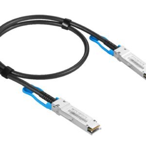
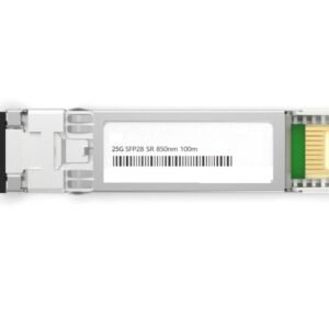
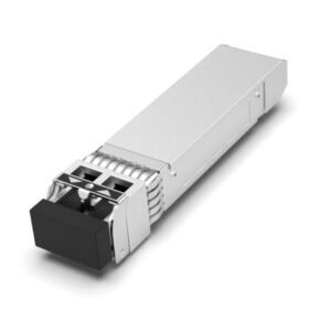
Description
| Absolute Maximum Ratings | ||||
| Parameter | Symbol | Min | Max | Unit |
| Storage Ambient Temperature | TSTG | -40 | 85 | ℃ |
| Relative Humidity(Non-condensing) | HS | 5 | 90 | % |
| Power Supply Voltage | VCC | -0.3 | +3.6 | V |
| Input Voltage | VIN | -0.3 | VCC+0.3 | V |
| Damaged Threshold,per Lane | DT | 3.0 | dBm | |
| Recommended Operating Conditions | |||||
| Parameter | Symbol | Min | Typical | Max | Unit |
| Operating Case Temperature | TC | 0 | 70 | ℃ | |
| Operating Humidity | Rh | 5 | 85 | % | |
| Data Rate,per Lane | DR | 25.78125 | Gbps | ||
| Power Consumption | PW | 2.5 | W | ||
| Electrical Characteristics | ||||||
| Parameter | Symbol | Min | Typical | Max | Unit | Notes |
| Power Supply Voltage | VCC | 3.13 | 3.3 | 3.47 | V | |
| Power Supply Current | ICC | 750 | mA | |||
| Transmitter | ||||||
| Differential input impedance | Rin | 100 | Ω | |||
| Differential data input swing | Vin,pp | 180 | 1000 | mV | ||
| Single ended input voltage
tolerance |
VinT | -0.3 | 4.0 | V | ||
| Receiver | ||||||
| Differential data output swing | Vout,pp | 300 | 850 | mV | ||
| Single-ended output voltage | -0.3 | 4.0 | V | |||
| Optical Transmitter Characteristics | ||||||
| Parameter | Symbol | Min | Typical | Max | Unit | Notes |
| Center Wavelength | λout | 840 | 850 | 860 | nm | |
| Average Launch Power each
lane |
Pout | -8.4 | 2.4 | dBm | ||
| Optical Power OMA, each Lane | POMA | -6.4 | 3 | dBm | ||
| Transmitter and dispersion eye
closure(TDEC),each lane |
TDEC | 4.3 | dB | |||
| Spectral Width (RMS) | σ | 0.6 | nm | |||
| Optical Extinction Ratio | ER | 2.0 | dB | |||
| Transmitter and Dispersion
Penalty each lane |
TDP | 3.5 | dB | |||
| Optical Return Loss Tolerance | ORL | 12 | dB | |||
| Average launch power of OFF
transmitter, per lane |
-30 | dBm | ||||
| Transmitter eye mask
definition{X1,X2,X3,Y1,Y2,Y3} |
{0.3, 0.38, 0.45, 0.35, 0.41, 0.5} | 1 | ||||
| Optical Receiver Characteristics | ||||||
| Parameter | Symbol | Min | Typical | Max | Unit | Notes |
| Receiver Wavelength | λin | 840 | 860 | nm | ||
| Average Receive Power per
Lane |
RXPx | -10.3 | 2.4 | dBm | ||
| Stressed Receiver Sensitivity in
OMA |
SRS | -5.2 | dBm | 1 | ||
| LOS Assert | LOSA | -30 | dBm | |||
| LOS De-Assert | LOSD | -13 | dBm | |||
| LOS Hysteresis | 0.5 | dB | ||||
| Receiver Reflectance | Rfl | -12 | dB | |||
Notes:
1. Measured with a PRBS 231-1 test pattern, @25.78125Gb/s, BER<5E-5.
| Parameter | Accuracy | Calibration | Note |
| Temperature | ±3°C | Internal | 0~70℃ |
| Voltage | ±3% | Internal | 3.1~3.5V |
| Bias Current | ±10% | Internal | Specified by normal value |
| TX Power | ±3dB | Internal | -8.4~2.4dBm |
| RX Power | ±3dB | Internal | -10.3~2.4dBm |
| Parameter | Accuracy | Calibration | Note |
| Temperature | ±3°C | Internal | 0~70℃ |
| Voltage | ±3% | Internal | 3.1~3.5V |
| Bias Current | ±10% | Internal | Specified by normal value |
| TX Power | ±3dB | Internal | -8.4~2.4dBm |
| RX Power | ±3dB | Internal | -10.3~2.4dBm |
*Note:
1.Measured with a PRBS 231-1 test pattern, @25.78125Gb/s, BER<5E-5. 2.Receiver sensitivity in OM


